Operator Library: Hardware Platform
The LED operator provides an interface for accessing the board user LEDs of the frame grabber via the applet.
Driving a logic HIGH on the input forces the correspondent board LED to light on. Driving a logic LOW on the input forces the correspondent board LED to light off.
For the exact location of board LEDs on the frame grabber, see the manual of your frame grabber.

|
|
On marathon VCX-QP, the numbering of the LEDs is mirrored, see parameter description of parameter Port below. |
Resources
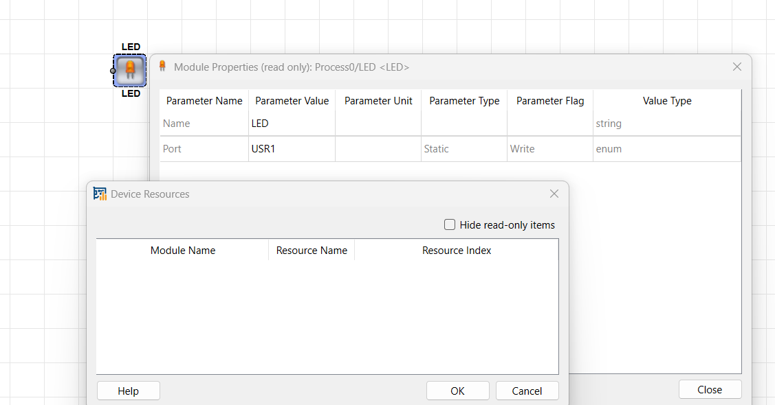
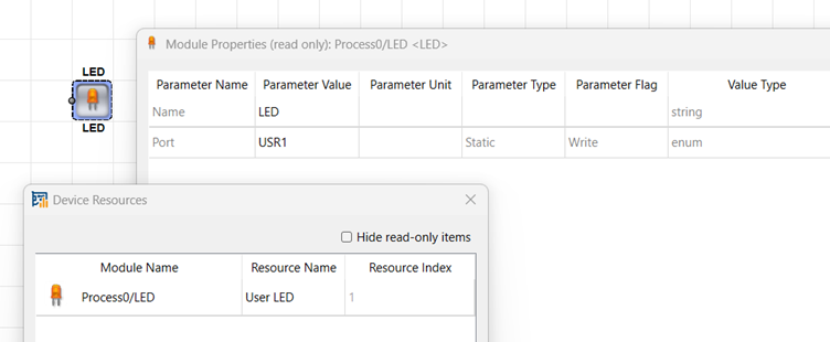
The operator mirrors the Port parameter settings into the dialog as read-only parameters. You can see the FPGA device resources, if you open the dialog from the menu. The device resources are read-only:
For the imaFlex 2 Dual 100 platform, the operator is using a read-only resource of type User LED, which is influenced by the Port operator parameter. The User LED resource index is always the Port label value, i.e., USR1 is mapped to the User LED resource index 1 and USR6 to the User LED resource index 6.
| Link Parameter | Input Link I |
|---|---|
| Bit Width | 1 |
| Arithmetic | unsigned |
| Parallelism | 1 |
| Kernel Columns | 1 |
| Kernel Rows | 1 |
| Img Protocol | VALT_SIGNAL |
| Color Format | VAF_GRAY |
| Color Flavor | FL_NONE |
| Max. Img Width | any |
| Max. Img Height | any |
| Port (imaflex, mE5 marathon, and LightBridge VCL platforms) | ||||
|---|---|---|---|---|
| タイプ | static write parameter | |||
| Default | USR1 | |||
| 範囲 |
imaFlex 2 Dual 100, imaFlex CXP-12 Penta, and imaFlex CXP-12 Quad: {USR1, USR2, USR3, USR4, USR5, USR6} LightBridge VCL, mE5 marathon VCLx, and mE5 marathon VCL: {USR1, USR2} mE5 marathon VCX-QP and mE5 marathon VF2: {USR1, USR2, USR3, USR4} |
|||
|
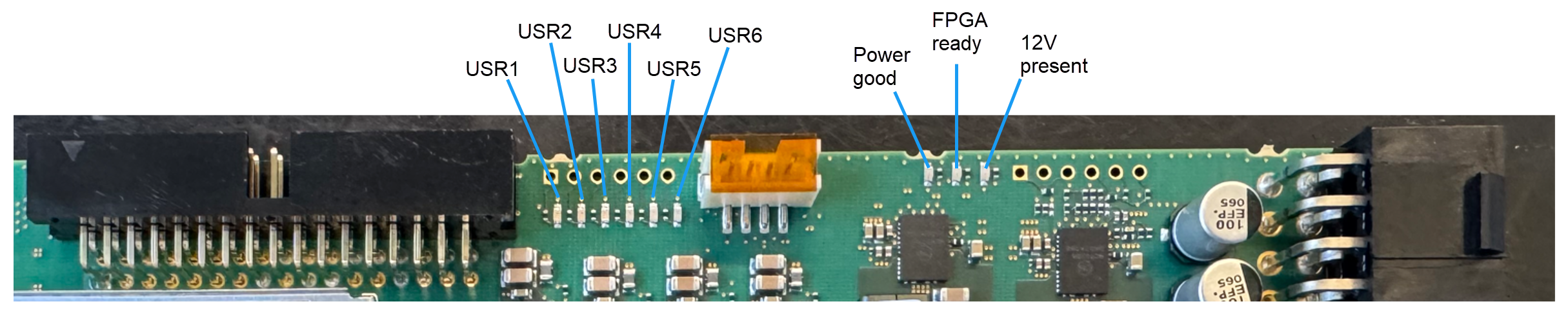
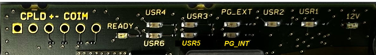
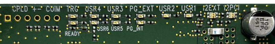
The parameter defines which of the board LEDs will be connected by the operator. imaFlex 2 Dual 100, imaFlex CXP-12 Penta and imaFlex CXP-12 Quad:
On the imaFlex 2 Dual 100, the board LEDs are located in the following positions: On the imaFlex CXP-12 Penta, the board LEDs are located in the following positions: On the imaFlex CXP-12 Quad, the board LEDs are located in the following positions: mE5 marathon VCLx, mE5 marathon VCL, LightBridge VCL:
mE5 marathon VF2:
mE5 marathon VCX-QP:
To turn the LED ON, the input I must be driven HIGH. To turn the LED OFF, the input I must be driven LOW.
|
||||
![[Important]](../common/images/admon/important.png)
| Pin_ID (ironman platforms) | ||||
|---|---|---|---|---|
| タイプ | static write parameter | |||
| Default | 0 | |||
| 範囲 | [0;3] | |||
|
The Pin_ID parameter defines which of the 4 board LEDs will be connected by the operator. Range is [0; 3].
|
||||
The use of operator LED is shown in the following examples:
-
An example for hardware self test of DMA, RAM, GPIOs, Trigger and LEDs.
